Continuing on....

Step 21
[ ] Remove the two highlighted bosses (plastic standoffs)
Step 22
Note: The 1uF capacitor is used in this step. It is marked "105" and is on a
paper carrier. It mounts next to the lockout chip in place of the one that was
removed earlier.
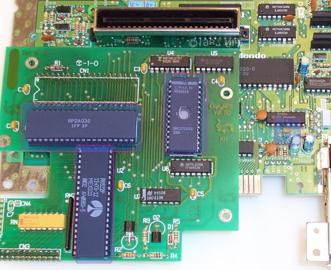
[ ] Carefully install the chips. When installing them, hold onto the bottom
of the CopyNES board and push the chip in. Do not push the chip in while
holding the back of the NES board or else it could come unplugged, or the
pins could bend or something.
[ ] Drop the CPU into U1, noting polarity!
[ ] Drop the 6522 into U2, noting polarity!
[ ] Drop the EPROM into U3, noting polarity!
[ ] Install the 1uF monolytic cap (marked 105) near the lockout chip
Note: If you used a 1uF polarized cap, make sure the POSITIVE side of the cap
goes to the large copper "ground plane" (which is really at 5V) and the negative
side goes to pin 7 of the lockout chip.
Step 23
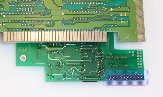
[ ] Solder the 26 pin dual row header onto the board so that it sticks up from
    the back side of the CopyNES board as shown.
Step 24
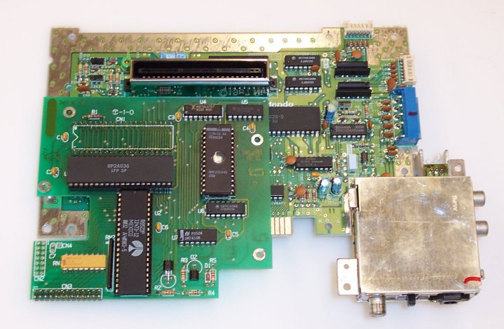
If all goes well, your CopyNES board should look like this!
Step 25
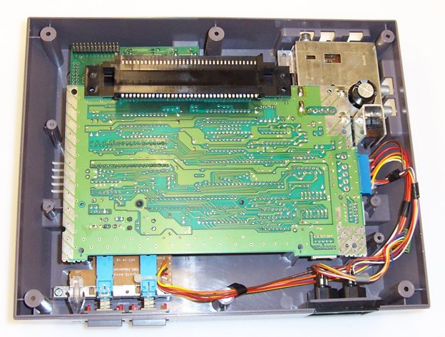
Drop it into the bottom half of the NES case.  It should sit in there almost perfectly.
Note that it is normal if the board isn't 100% flat on the top of the bosses (plastic
standoffs) that hold it down.  So long as this error isn't more than 1mm or so, things
will be fine.  This should be the case with the 40 pin headers I sell with the kits.
If your header is too large however (since you wanted to make your own or whatever)
you can cut down the plastic "hump" on the inside of the case to make it fit.

At this time, I suggest testing the unit out.  Plug the cart port back on, and connect
the large blue connector (you don't have to connect the smaller green ones at this time)
Now, install a cart and use another cart to weigh it down so that it makes good contact.
Turn the NES on, and the game should come up.  If it doesn't, recheck your work and
look for solder shorts, unsoldered connections, etc.
Step 26
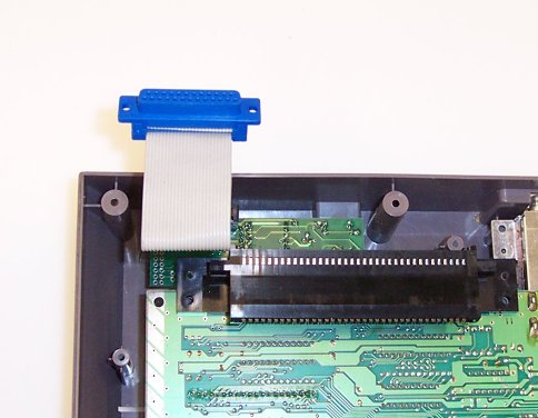
[ ] Attach the cable so that the stripe is facing the left.	 When plugging the cable
    in, be sure to support the bottom of the CopyNES board.  Otherwise, the board
	will flex down and possibly damage something.
[ ] Re-attach the two green controller connectors.  Player 1 is on the front, and
    Player 2 is on the side.

If you REALLY want to try making the IDC cable, here is how.

Test the unit by hooking it up to your PC and using the host code. If it doesn't work,
check the IDC connector, and your cable, and parallel port settings.  The cable
required to connect the CopyNES unit to your PC is a male/male DB-25 to DB-25
straight through cable.

You are now done!  You can now dress your unit up by painting it, cutting a hole for the
DB-25, etc.

