Prototype #3
The board has been spun. :-) I designed a board and got it fabricated. Here's the goods.
 Top-down view of the whole works.
This is a totally new prototype with everything I wanted to add to the old ones but never did. It is electronically 100% complete, other than I may stick an IR receiver on it so it can be remote-controlled.
 View of everything.
The board is designed to stack behind the display; however for prototyping and testing I can't do this so the board is really 180 degrees rotated from what it will be when finished. The trimpot sticking up on two wires is for setting the oscilloscope gain... I was trying to get the "perfect" level, then I can replace the pot with a fixed resistance. The holes for this resistor can be seen in the next picture.
 Main board.
This is the main board. There are 4 processors on here: two PIC17C42's, a PIC16F874, and a 65816. The three PICs run at 24Mhz while the 65816 runs at 4Mhz. A Xilinx FPGA replaces all the glue logic and interface logic for this circuit.
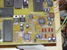 Analog section.
Close-up of the analog section. I decided to go with all through-hole parts on this design for the fun of it. There's a large ground plane on the bottom underneath this stuff. It is very, very quiet and I can't hear any hiss, power supply whine, or digital hash. I do need to clean that flux off of there. It showed up really bad on the photo.
|


