Peltier-Powered Drink Cooler!
Page 2
desktop-sized can cooler
Peltier Block
From the "Something that Should be Made Department" comes this drink cooler. Ever since seeing peltier devices for sale I have wanted to put one to a cool use, and this is it. :-) The heart of the device is of course the peltier module.
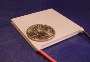
(photo is from ebay auction for my peltier)I got the peltier I used (pictured above) off of ebay for about $20 after shipping and such. It was in new condition when received. If you are going to make this project or use a peltier in anything make sure it is new. A used peltier may have water damage, and may not function at all or inadequately. Also, the device should have a perimeter seal to prevent moisture getting inside. This unit has an RTV seal. Specs on my unit are:
Size: 50mm*50mm*3.9mm To use a peltier, it must be mounted on a (large!) heatsink. Running a peltier without a heatsink on the hot side will cause it to overheat and fail nearly instantly. The device generates TWO forms of heat which are transferred to the heatsink: the actual wattage of the power used, (the peltier appears as a purely resistive load) and the heat pumped from the cold side. OK, enough peltier theory. Onto the project.
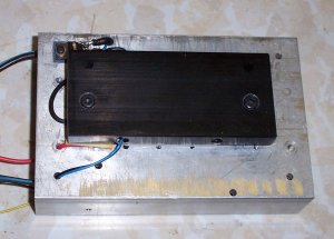
This is the peltier block I constructed for the device. I had some aluminum scraps laying around, and happened to have some 2" wide bar stock with 4 holes drilled in it in favorable positions. I used a larger drill bit to "over-drill" the two holes I used so that the heads fo the bolts would be flush with the top surface. I then drilled 2 holes in the heatsink and tapped them for the 10-24 bolts. Then, I greased the peltier with some white thermal grease and installed the aluminum bar over the top, being very careful not to crush the peltier! (this is very easy to do if pressure isn't even on both bolts). There were 2 threaded mounting holes in the side of the bar, so I filled one full of epoxy and stuck an LM335 on wire leads (soldered wires to the leads and heatshrunk them indivually, then put shrink over that) into the hole. The end result is a very rugged and water-proof temperature sensor that will track the "cold" side very well. The black and blue wires coming off the bar are visible at the bottom left of the pic.

This side view shows the cold side temp sensor pretty well and the RTV seal on the peltier.

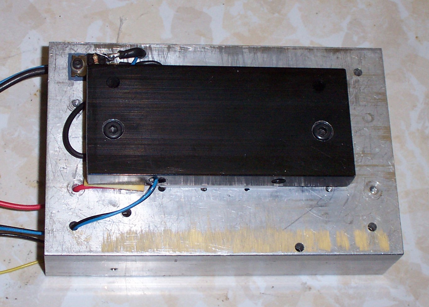
Bottom of the heatsink- The "hot" side temp sensor can be seen in the middle. It is another LM335 clamped to the underside of where the peltier mounts. This should track it pretty well. I drilled a hole through all the heatsink fins to pass the black and yellow wires through so that they exit with the blue and black (cold side) wires. The red wire near the top is for the positive connection to the peltier. The heatsink was used and there were a shitload of pre-existing holes. Ideally the sink should be clean and new, but I don't think the holes will reduce efficiency enough to matter.
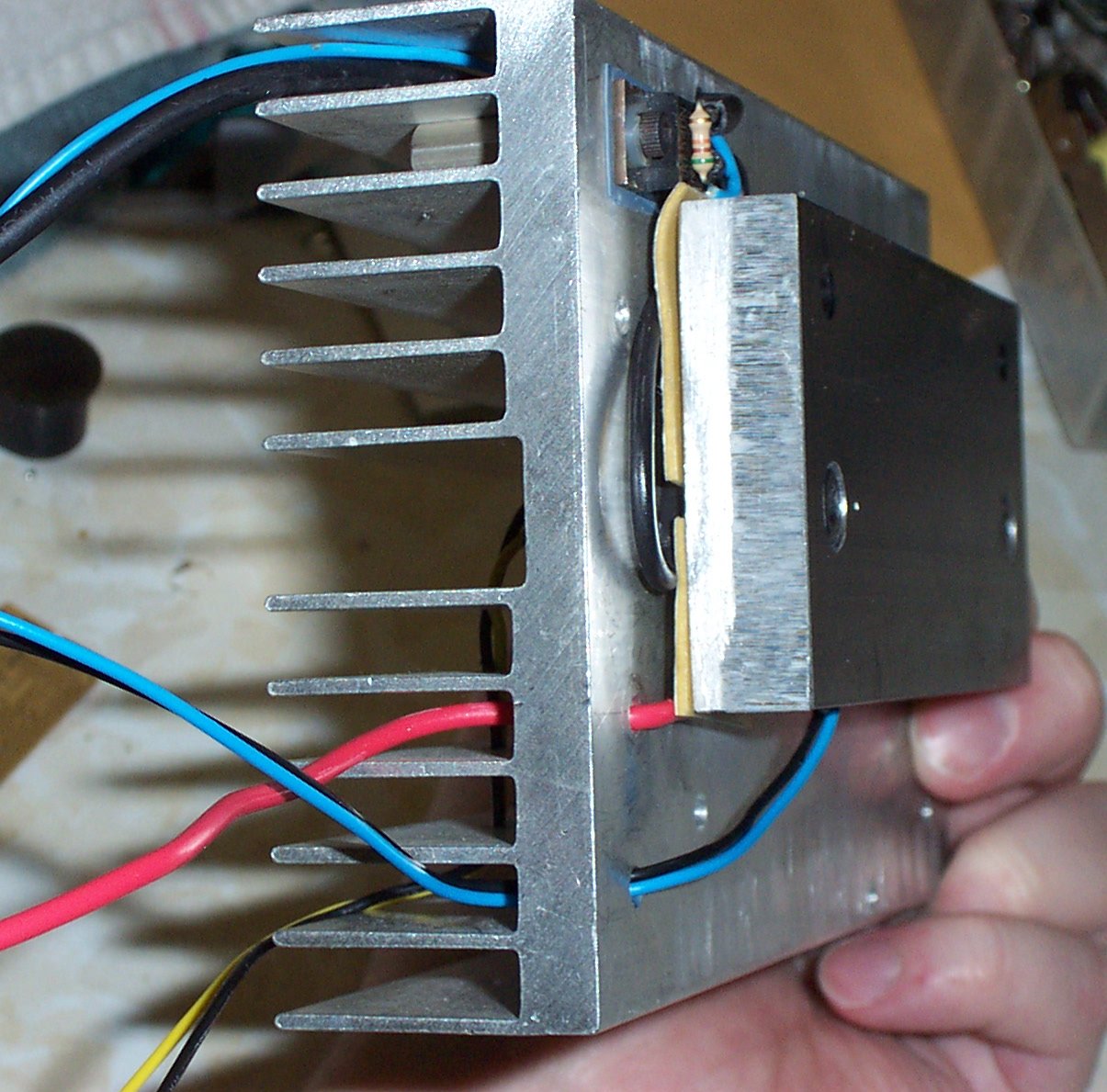
A side view of the whole rig, showing the wires better. I put some foam double stick tape between the wires and the cold block to keep them away. They could add heat to it (via conduction), reducing efficiency of the thing. The IRL540 n-channel FET can be seen in the upper left. The fat black wire connects to the source on the FET, and the drain of the FET connects to the negative side of the peltier. The thin blue wire connects to the gate of the FET. I stuck a 51K resistor across the drain and gate so that if it was disconnected, the FET would turn off and not get stuck in its linear region. That could be very, very bad causing the FET to dissipate lots of heat and possibly melting or exploding!
It may be wise to review the schematic before continuing onto the next part.

This is the control board for the device. It uses a PIC18F242 microcontroller to run the show. This PIC has a built-in ADC on it and I use this for reading the temperature of the two sensors. The board that the LEDs and buttons are on came from an old PCB I found. it just happened to be exactly what I needed :-) It also significantly simplified things since I didn't have to multiplex the LEDs and mount them and such.

Back view, showing the three connectors. In order from left to right: fan, temp sensors, power/FET output. The blue pot adjusts the reference voltage for the PIC's ADC. It must be 2.560V or else the ADC will not have the proper step size. A word about that- the PIC has 1024 steps on its ADC, and the ref is 2.56V so each step of the ADC is 2.56/1024 or 2.5mV. The LM335 temp sensors change 10mV per degree Celcius. These devices read out in kelvin, which at room temp is around 2.8V or so... too high for the PIC's ADC at 2.56V ref. I used the 12.K resistors to divide the output of the LM335's by 2 so that each degree is 5mV... exactly 2x what the PIC's ADC step size is. This means that for each step on the ADC, the temp has to change exactly .5 degrees C. So this means my ADC will now read out directly in degrees C. :-) I don't have to do a messy conversion in software.

Top down view. The circuit is pretty simple and it only took me a couple hours to make it. The PIC socket is still empty here. There's a...
|
