Click on any picture for a larger view.

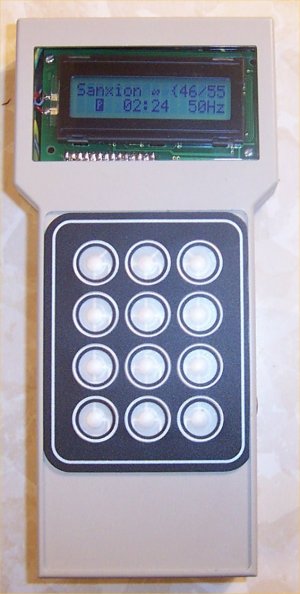
The final result. All that is left is to make a bezel for the LCD display, and button inserts for the keypad.

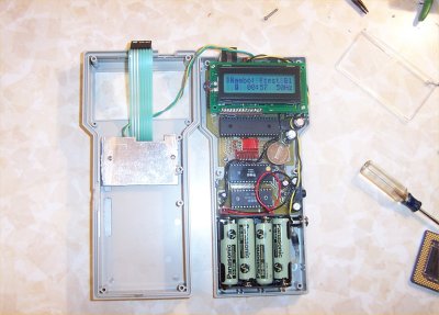
Opened up. The heatsunk transistor on the top of the enclosure is the pass transistor for the NiMh fast-charge
circuit. The 8 AA cells are at the bottom, along with the power input jack.

The 512K RAM chip, backlight inverter, and most of the larger power supply components mount under the
LCD display.

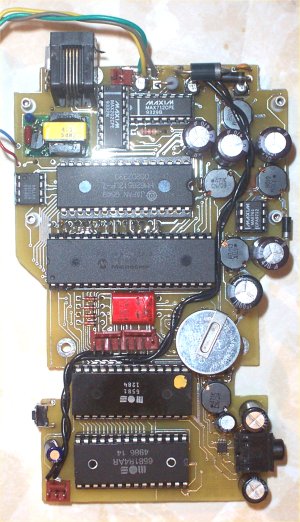
Top of the PCB Closeup. Sorry about the flash glare.

Bottom of the PCB closeup. A hole was cut in the PCB to drop the inverter through. This was done to make sure
there was enough clearance for the LCD. Also, the rubber feet makes sure the board does not buckle when it is
installed in the enclosure. The power supply can be seen in the upper left hand corner of the board. It does not
require heatsinking since it is 92%+ effecient.
Movies
 Playing a tune. Sorry about the colour balance shifting. Camera doesn't like light blue I guess. Playing a tune. Sorry about the colour balance shifting. Camera doesn't like light blue I guess.
 The "beta" register viewer. I have finished this but haven't taken a movie of it yet. The "beta" register viewer. I have finished this but haven't taken a movie of it yet.
|


