ML-1 Serial Board
Part Number 1531
|

Status: Fully traced out and processed. Schematic generated binary for the 1702 EPROM on this board.
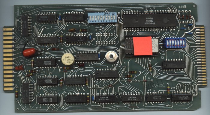
Front of this board. (thanks to Lord Nightmare for the scan)
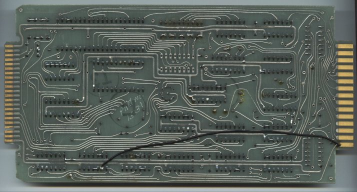
Back of this board. (thanks to Lord Nightmare for the scan)
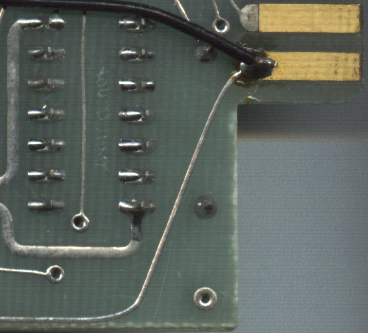
There is some very small text scratched on the board by a route fix that says "you dummy". This appears to have been added at the factory!! (thanks to Lord Nightmare for the scan)
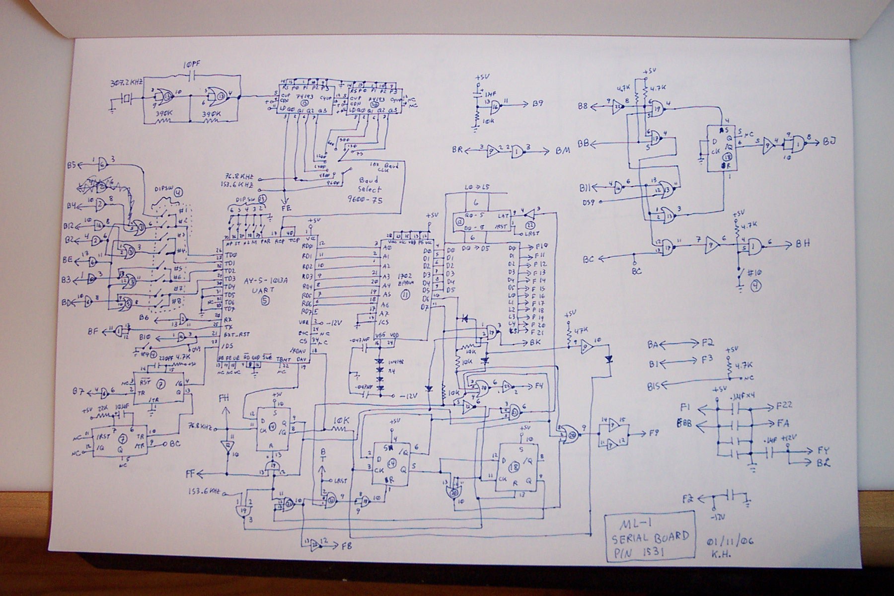
Schematic of this board. (note: clicky for larger)
Description: The output of the UART is run through the EPROM (lower 7 bits. The 8th bit is thrown away). Only the lower 128 bytes of the EPROM are used. A7 is grounded. The board is designed to route bit 7 of the UART output to A7, but it is jumpered to only allow 7 bit data. The bank of 7 dip switches select various UART options, such as parity, stop bits, data bits, etc. Only 5 of these switches are used, however. The upper 2 bits of the EPROM's data outputs are used to control various things on this board relating to how speaking is initiated, and similar things like that. Each phoneme that is sent to the ML-1 requires TWO bytes- the phoneme byte and a "control" byte for inflection control. The bottom 6 bits of the EPROM's data outputs are used for this function. There is a 6 bit latch which latches the phoneme, then when the second byte is written, this latched value and the EPROM data contents themselves are written to the FIFO, forming a 12 bit word. There is a somewhat complicated circuit which does this two byte write function, composed of several flipflops and some discrete logic. Writing the "start" code will prevent it toggling for example, since it's only a 1 byte command code. A few of the other command bytes will do this also, but they aren't fully understood yet. There is an absolutely complicated setup to return 40h through 4fh on the RS-232 back to the host system. The upper 4 data bits on the UART's transmit side are hard wired, while the other 4 bits run through 8 of the 10 switches on the 10 position dip switch. These are then connected to an unholy mess of RS-232 level translators and things to report the state of control lines on the serial lines (apparently). This doesn't seem very useful to me, but there it is. The other 2 dip switches (#9 and #10) control more immediate functions. #9 controls reset to the UART. When on, the UART will function normally. When off, the RS-232 port can hold the UART in reset! Kinda odd. Dip #10 will disable what I believe to be hardware flow control. I won't know for awhile yet if this is its function or not. That's about all there is to the serial board. |
