
Tech of the Famicombox
|

The two parts of the backpanel screw into a black plastic frame.
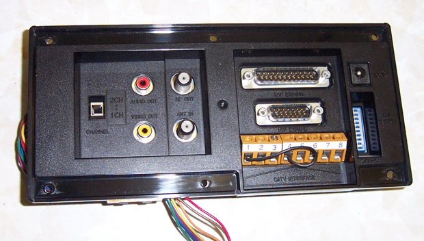
Front view of the plastic frame. The connections are RF in, RF out, audio out, video out, channel 1/2, "25P expand", "15P expand", "CATV interface", power, and the 10 position dipswitch. Interestingly, the 15 pin connector is identical to the one found on the regular Famicom, so this thing could potentially use any Famicom peripherals.

The modulator and assorted I/O then screws into the backpanel, and a large ribbon cable attaches it to the main PCB.

The back is then screwed onto the box after connecting it up to the PCB. The expansion connector is hidden under the black plastic cover on the lower left.

Here's a straight top down shot of the guts with everything installed, minus the power supply.

And a somewhat closeup of the PCB area showing some of the connections. The empty black cart connector sticking up on the right of the PCB is for the menu cart board.
|
