Colordreams Attempt #3

196 board

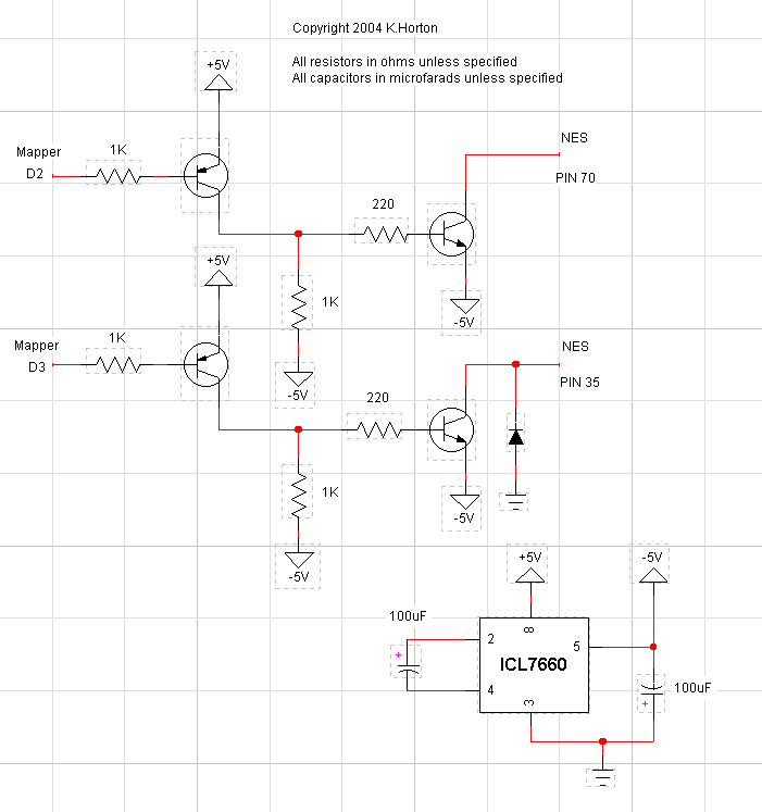
Circuit Diagram
How it works:
They seemed to have learned that the Rube Goldberg circuitry with the germanium diode was
not required. This is a refined version with that missing. Like the others, the software
must operate this lockout defeat during startup for it to work properly.
Circuit Operation:
The ICL 7660 chip generates -5V using 2 capacitors. There are two identical circuits here
which are simply voltage translation, so that the 5V logic from the mapper chip can switch
the -5V on and off to the lockout pins. I don't know why there is a diode on pin #35-
it is effectively shunting the -5V supply to ground when the transistor turns on.
When D2 (or D3) is high, it turns -5V on to its respective cart pin.
|


