
Tech of the Famicombox
I got bored awhile back and decided to reverse engineer this thingy to see exactly how it works. It is quite interesting to say the least. There is ALOT of hardware on here. I should probably get the bad news out of the way first: This thing cannot run later games that use the MMC3 or anything which uses IRQs, and anything that maps stuff outside the area of 8000-FFFFh. Also, the games use a special lockout chip only found in these special black carts... not to mention the special PCBs in them too. They connect the 4 address lines on the lockout chips to 4 of the expansion connector pins. The lockout chips in the carts are then "networked" together, along with the menu cart's chip. See my lockout chip documentation for more information about how this is done.During startup, the unit queries each cartridge slot to see if a lockout chip is present. If it is, the game is marked as being OK, and its name is determined. If the lockout chip is missing, or if a game name cannot be determined, the unit will go to the next. If no carts are found, it replies "CASSETTE ERROR" and then hangs.

Since I started the project with a fully disassembled unit, I'll go in order of reassembly. Here's the main PCB. It contains a standard NES/Famicom chipset with the PPU and CPU. One thing to note is that the CPU is a revision E part, instead of the more common revision G part found in US NES consoles. I'll discuss the actual guts of the PCB later on. There is an aluminum heatsink glued onto the top of the PPU for some reason.
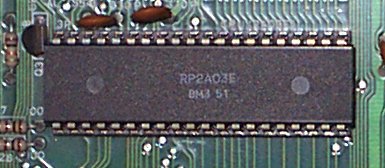
Here's the revision E CPU on the board. Supposidly this revision does not support looped or "periodic" noise. I will be testing this theory later on when I get a chance. I do know this chip supports DPCM, since the DPCM in Duck Hunt works fine.
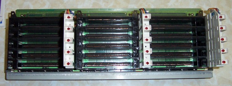
This is the top of the cart board. The 15 carts slide into these slots. The front door keeps them captive in the sockets. There is a red LED next to each cart slot which lights up when the game is being played. During cartridge detection and the demo mode, the LED flashes next to the currently tested/shown game.
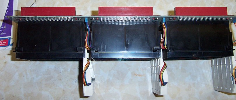
Side shot showing the various plastic supports and things for the cart sockets.
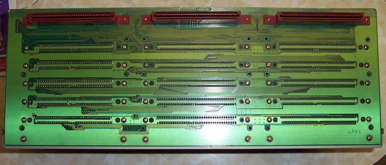
Back of same. If you look closely, you can see some of the pins were cut and bent near the middle of the sockets. Guess someone screwed up on the board layout- These are for the lockout chip's address lines. Whoops!
One sad looking empty Famicombox case!
|
